English Instruction Book November 1931 (Reprinted 1934)
Copyright © Kelvin Diesels PLCKELVIN SLEEVE VALVE ENGINES The Running and Repairing of
ALL MODELS
(Petrol Only)
1. IF this instruction book contains few illustrations it is because our designs have been constantly copied by certain of our competitors. An entire model has been imitated both in this country and in China. Our reversing gear, silencer, lubricating system and folding propeller have all been closely imitated by British makers. Our guarantee has just been reproduced in its entirety. You will, however, have no difficulty in following these instructions with the engine before you, and we advise you to make yourself familiar with the carburettor and pump by taking these parts completely to pieces Any advice we can give is at your service whether you are the original purchaser of the engine or not. When writing, do not omit to quote the number of the engine stamped on the crankcase.
2. TOOL BOXES.--A box of tools accompanies each engine. It is closed with a lead seal, and, if delivered with the seal broken, its contents should be checked with the list to be found in the engine catalogue. Fix up the oil can by its clip in some convenient position.
3. REPLACEMENTS.--All the parts of current models are always in stock, also the parts of our oldest models for which there is a regular demand Please describe the parts which you require in the terms of the illustrated price list which is contained in the tool box. We carry in stock boxes contain a selection of spares suitable for customers in remote districts: contents and price as per price list. To England, Scotland. Northern Ireland, Isle of Man and the Channel Islands, goods not exceeding eleven pounds weight (in each package) may be sent by post C.O.D. (cash on delivery). Buyers abroad may have goods sent C.O.D. if they satisfy themselves that the system is available.
4. IMPROVEMENTS.--We make improvements from time to time, and, where possible, we design them so as to be applicable to engines already despatched. If you wish to know whether any improvements have been added since your engine was made and the cost of applying them, quote the number of the engine to us.
5. LUBRICATING OIL.--Lubrication is the most important care of an oil engine. Use good oil such as is sold for motor cars, and see that it is delivered to you with the maker's seal intact.
We recommend--
CASTROL AA
C. C. Wakefield& Co.. Ltd., Cheapside. London E.C.2.
MOTORINE D
Prices Patent Candle Co., Ltd., Belmont Works, Battersea, London, S.E.
GARGOYLE MOBILOIL A
Vacuum oil Co., Ltd., Caxton House, Westminster, London, S.W.1.
TEXACO MEDIUM
Texas oil Co., Ltd., 125 Strand, London W.C.2.
All authority to sell oil under our registered mark KELV0L has been withdrawn.
6. THE LUBRICATOR should be filled with oil (par. 5) and replenished when empty. The knob should be pressed down once per hour of running. If the running has been at reduced speed, the knob should be depressed only to a limited extent. The base of the lubricator contains a piston, which forces the oil into the crankcase. A spring raises the piston after it has been depressed. A collar on the stem limits the travel of the piston, which should be as follows :--
Model A2, running up to r.p.m., travel 1 3/16" Model A2, running up to r.p.m., travel 1 7/16" Model A2, running up to r.p.m., travel 1 3/4" Model A4, running up to r.p.m., travel 2 5/16" Model A4, running up to r.p.m., travel 2 15/16" Model A4, running up to r.p.m., travel 3 1/2"
Model B2, running up to r.p.m., travel 1 7/16" Model B2, running up to r.p.m., travel 1 3/4" Model B2, running up to r.p.m., travel 2 1/16" Model B4, running up to r.p.m., travel 2 7/8" Model B4, running up to r.p.m., travel 3 7/16" Model B4, running up to r.p.m., travel 4"
Model C2, running up to r.p.m., travel 1 3/8" Model C2, running up to r.p.m., travel 1 3/4" Model C2, running up to r.p.m., travel 2 1/16" Model C4, running up to r.p.m., travel 2 3/4" Model C4, running up to r.p.m., travel 3 1/2" Model C4, running up to r.p.m., travel 4 3/16"
LUBRICATING OIL FOR "KELVIN" ENGINES
The Bergius Company accepts no responsibility for the choice of lubricating oil and grants no authority to sell oil under the registered marks "KELVOL" or "KELVIN" but the following brands appear to give satisfaction to users :--
FOR "KELVIN-DIESEL" ENGINES Essolube 30 Adcol R.J. Ilo Diesel Oil, Heavy Germol 34 Motorine 'D' Diesa "E" Special Shell C.Y.2 Speedolene T Texaco Algol Veedol Medium Gargoyle DTE, Extra Heavy Castrol 'XL' Wellsaline Valvo, Medium
FOR "KELVIN" ENGINES (poppet valve) Motorine 'B' or 'C' Texaco, Heavy Gargoyle Mobiloil 'BB' Castrol 'C'
FOR " KELVIN-SLEEVE" AND "KELVIN-RICARDO" ENGINES Motorine 'D' Texaco, Medium Gargoyle Mobiloil 'A' Castrol 'AA' 7. CRANKCASE should be cleaned out every 100 hours of running. If this is neglected grit and burnt oil accumulate and destroy the bearings. Any evidence of water such as rust on the bright parts should be investigated at once.
8. OIL LEAKAGE from any part of the engine may result in lack of lubrication and should be investigated at once.
9. ENGINE INCLINED.--An Engine stopped at any time should contain in each division of the crankcase sufficient oil to reach the point of the crankpin bolt. The sloping oil ducts visible within the crankcase keep the oil constantly circulating from the rear to the front, ensuring that the forward piston gets its share, even although the engine may be inclined to the extent of 1 inch in 10. As the engine must not be worked at a greater inclination than 1 in 10, it is advisable to measure the inclination when the boat is at full speed. This may be done either with a spirit level laid on some part of the engine, or with a plumb line held in front of the flywheel.
10. CARE OF ENGINE.--Kelvin engines are designed to be easily kept clean, all parts are rounded, no sharp edges. Use cotton waste obtainable from chandlers old cloth is not suitable, keep your waste dry. Wipe your tools each time you use them.
11. BEFORE STARTING A NEW ENGINE.--Work the pumps by hand until water issues from the exhaust pipe. See that the crankcase contains sufficient oil (9) to reach the split pin of each crank when in its lowest position. Fill the lubricator with oil. Put into the reverse gear case the quantity of oil mentioned on the instruction plate. Oil the minor parts, lower starting wheel and pawls, governor, governor lever, chains.
12. STARTING. MODELS A.
- Detach the stopping wire.
- Turn on petrol at tank, float chamber, and pilot cock.
- Prime manifold, retard ignition (lower lever down).
- Completely close throttle (upper lever up).
- Put reverse gear at neutral (knob on wheel down).
- Turn handle smartly.
When engine starts advance spark (lower lever up) put in clutch and open throttle gradually. If engine threatens to stop, promptly close throttle and keep engine running slowly until it has warmed up a little. See that pumps are working.
STARTING. MODELS B. AND C.
- Detach the stopping wire.
- Turn on petrol at tank, float chamber, and pilot cock. Prime cylinder tops, retard ignition (lower lever down).
- Completely close throttle (upper lever up).
- Put reverse gear at neutral (knob on wheel down). Work starting handle up and down (slowly).
- When engine starts advance spark (lower lever up) put in clutch and open throttle gradually.
- If engine threatens to stop, promptly close throttle and keep engine running slowly until it has warmed up a little.
- See that pumps are working.
- See that all cylinders are firing by opening priming valves (62).
13. TO STOP ENGINE.--Retard ignition (lower lever down). close throttle, place the stopping wire on the brass terminal.
14. ENGINE NOT FIRING PRIMING.--Causes :-- (a) over primed-turn engine with priming valves open; (b) poor petrol-heat sparking plugs; (c) lack of spark, test plugs (27); (d) magneto contact breaker stuck-remove small cover (21); (e) impulse starter not working (30); (f) magneto wrongly set, see instruction plate; (g) sleeve driving mechanism wrongly set, turn engine till the hole in No.1 sleeve appears in centre of "peep" hole, see that No.1 crank is up and mark on flywheel central, repeat operation for each cylinder in the following rotation: 1, 2, 4, 3 for 4 cyl. engines, 1, 2, 0, 0 for 2 cyl. engines; (h) sleeve mechanism damaged examine it (58 and 60).
15. ENGINE FIRES PRIMING AND STOPS.-- Causes:-- (a) lack of petrol, see that there is a flow at drain cock; (b) pilot jet choked; (c) air leak in pipe connecting pilot with float chamber, tighten coupling nuts; (d) throttle valve not completely closed (34); (e) over primed, turn engine with priming valves open; (f) lack of compression due to wear inside sleeve at top, renew sleeves and cylinder heads.
16. ENGINE RUNNING IRREGULARLY.-- Causes:-- (a) sparking plugs missing, open priming valves one by one to ascertain which is missing (28); (b) lack of fuel, see that there is a full flow at the float chamber drain cock; (c) air lock in pipe line due to tanks being run empty, blow into tank; (d) water in fuel, open drain cocks of tank and float chamber; (e) choked spray jet, accessible by removing screw plug; (f) fuel down to level of warning device (75).
17. ENGINE SPITS FIRE AT AIR INLET.--Causes:-- (a) air lock in pipes, blow into tank; (b) stoppage of spray jets; (c) stoppage of filter; (d) float chamber too low, raise it.
18. ENGINE STOPS WHEN SLOWED DOWN.--Float chamber too low, raise it. If fuel drips from vaporizer float chamber is too high.
19. CYLINDERS RUNNING HOT.--At full speed it should be possible to hold the hand on the pipe leading from the cylinder to the silencer (50).
20. MAGNETO, CARE OF.--Allow no oil or petrol to drip on to the magneto as that causes rapid wear of the platinum contacts. Keep the felt washer around the neck of the magneto spindle in good condition to prevent oil vapour from entering the magneto from the engine. 'The magneto requires only three drops of oil once a month.
21. MAGNETO CONTACT BREAKER.--The moving arm is liable to become stuck in damp climates owing to the swelling of its fibre bush. Remove the arm, polish and oil the pin; scrape out the fibre bush with the square tail of a small file or other suitable instrument. As this operation takes time, it is advisable to carry a spare contact breaker. The fibre pad on the end of the arm should be oiled, but no oil must reach the platinum contacts.
22. MAGNETO CONTACT BREAKER GAP.--The contact points are platinum tipped and gradually wear further apart, with the result that the gap increases. A gauge is attached to the magneto spanner; try it in the gap, and, if necessary, adjust the screw.
23. MAGNETO DISTRIBUTOR.--Some distributors have carbon brushes which wear. The dust produced must be removed from time to time. When the brushes wear down they should be renewed; the stretching of the spring serves temporarily.
24. MAGNETO REPLACEMENTS.--Owing to the great variety of magnetos which we have been obliged to supply, we cannot keep stock of all magneto replacements, and buyers are advised to communicate direct with the magneto maker, taking care to quote the number of the magneto if it bears one. A magneto sent to the maker should be labelled with the owner's name, and its despatch advised to the maker.
BOSCH MAGNETOS.
Bosch Limited,
Larden Road, Acton,
London, W.3.SIMMS MAGNETOS.
Simms Motor Units Ltd.,
Percy Buildings,
Gresse Street,
London, W.1.25. SPARKING PLUG, CARE OF.--Porcelain plugs must be handled with care. A spanner carelessly applied may produce in the porcelain an invisible crack which in time holds moisture and causes the plug to short. The thread of the sparking plug should be oiled.
26. SPARKING PLUG MISSING.--If due to soot bridging the gap, it may be cured without stopping the engine by detaching the terminal from the plug and holding it (by the cable) at some distance from the plug. The long spark thus produced intensifies the electric current. If missing is due to soot within the body of the plug, take it to pieces. If due to causes described in par. 25 throw it away.
27. SPARKING PLUG TEST.--Take out plug, lay it on engine so that its body alone makes contact, turn engine by hand. If no spark results (28).
28. SPARKING PLUG ADJUSTMENT.--The spark gap becomes wider with use, and the points should be bent to maintain the gap at .5 mm or 0.20 inch (gauge attacked to magneto spanner). The size of the spark is in proportion to the width of the gap. A spark too small may fail to start the engine, but a gap too wide may fail to produce a spark. A plug which sparks in the open air may not do so when exposed to the pressure within the cylinder, such a plug may start the engine if the priming valves are kept open. If the magneto is suspected of being weak keep the gap of the sparking plugs rather close, a small spark is better than no spark.
29. IMPULSE STARTER PRINCIPLE. MODELS B AND C ONLY.--Revolving with the magneto spindle are two pawls, which project when the engine is standing and recede when the engine starts. The projection of these pawls engages with a latch. The engagement of the pawl with the latch arrests the rotation of the armature and stretches a pair of springs. At a certain point the latch releases the pawl, and the springs impart to the armature a rapid motion which causes the magneto to produce a spark however slowly the engine is turned.
30. IMPULSE STARTER TEST. MODELS B AND C ONLY.--When the engine is turned by hand the impulse starter should produce a click twice per revolution The action may be observed by removing the cover from the end of the magneto. If the device is not working, remove the inspection door, taking care not to lose the spring.
31. THE FUEL SYSTEM.--The fuel flows from the tank to the float chamber, thence to the spraying jet located in a passage leading to the cylinder. Through this passage air is sucked by the engine. That part of the air passage in which the jet is located is restricted in size and is called the choke. The velocity of the air in the choke is sufficiently high to cause the jet to spray and impregnate the air with fuel. Petrol sprayed in an air current evaporates and produces gas. The float chamber controls the level of the fuel a little below the top of the spray jet and should be adjusted level, so that no overflow from the spray jet takes place when the engine Is stopped.
32. SPRAY JETS are all tested, and the number represents the actual flow through the jet. Never tamper with the orifice. If you wish to experiment get additional jets from us.
33. THE THROTTLE VALVE controls only the main supply of gas to the engine. The "pilot" has no throttle valve, and is just large enough to keep the engine running slowly when the throttle valve is closed (upper lever up).
34. THROTTLE VALVE ADJUSTMENT.--Detach the control rod from the throttle lever. Slacken screw in throttle lever so that lever may just be pulled around on spindle. Hold throttle valve in closed position (slot in stem fore and aft). by means of screwdriver. Pull lever full back. Reconnect control rod. Pull governor spindle hard out. Bind throttle lever to spindle. If correctly done there will be no play on throttle lever when governor stem is fully extended from governor case.
35. THE GOVERNOR.--The throttle valve is controlled by the governor, but the hand lever can be used to close the throttle valve against the action of the governor. When adjusting the governor we must estimate the speed to which the propeller will load the engine. If the governor is properly adjusted its spindle will be on the balance when the boat is at full speed (upper lever down). To raise the speed at which the governor acts remove a weight from each of the four governor balls. To lower the speed add weights-four at a time.
36. IF THE ENGINE STOPS TIGHT, feel immediately all the bearings of the crankshaft, sleeve driving mechanism and reversing gear to ascertain which has caused the stoppage. If none are more than hand hot the tightness must be due to some other cause (a) lack of lubricating oil (9), (b) sleeve tightness (37).
37. ENGINE BECOMES TIGHT AFTER STANDING.--This may be due to the presence of water about the sleeves. If the slackness in the sleeve chains cannot be pulled by hand from side to side the sleeves have become tight, pour paraffin into the cylinders, and by the flywheel gently move the engine in both directions. The cause of the water must be found at once or the engine may become ruined. Examine the exhaust manifold joint (49).
38. ENGINE KNOCKING.--If knock is within crankcase, look for something loose, misplaced, or running hot; (a) excessive soot within cylinders, remove water covers (63), clean cylinders one at a time (64); before starting see that you have the necessary joints; (b) too heavy a propeller may cause an engine to knock (72); or (c) slackness at the sleeve balls; (d) bearing slack (69) and (70).
39. REVERSING GEAR RUNNING HOT.--Causes:-- (a) excessive oil, drain case and put in correct quantity; (b) slipping clutch, due to an obstruction on the propeller or a bent blade; (c) heat generated at the rear bush (40).
40. BUSH AT REAR OF REVERSE GEAR RUNS HOT.--Causes:-- (a) lack of oil due to oil leakage (44), renew oil according to instruction plate; (b) shafts out of line, remove shaft coupling and check alignment of shafts with steel rule or blade of a carpenter's square (47). 8 levelling washers were supplied to be used below the engine as the foundation shrinks (77).
41. CLUTCH SLIPPING.--Causes:-- (a) Propeller blade bent; (b) shaft out of line (40, 47); (c) propeller of excessive pitch, Report engine number, dimensions and speed of boat r.p.m. of engine with throttle held full open; (d) control chain not correctly meshed (46).
42. CLUTCH, WORN OUT.--Causes:-- (a) Manipulating the clutch without first slowing the engine; (b) Running with the clutch slipping (41).
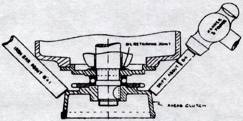
43. CLUTCH.--To remove the clutch from the crankshaft without damage, proceed as follows:-- Remove the nut which retains the clutch, hold a heavy iron bar (like the stock of an anchor) against the clutch on the port side while using a heavy hammer very lightly applied on the starboard side.
44. REVERSE GEAR LEAKING OIL.--Causes -(a) Bottom flange not tight or joint defective; (b) Breather pipe obstructed; (c) oil retaining joint at rear end of crankshaft defective, See illustration with par. 43.
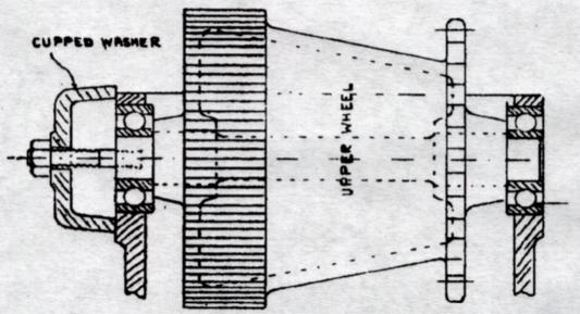
45. TO DISMANTLE REVERSING GEAR.--Remove cover, find spring link in chain, remove chain, detach case from engine. If it is necessary to remove the upper wheel draw out spindle with stud and cupped washer (in tool box) Do not remove upper wheel unnecessarily.
46. TO REPLACE REVERSE GEAR CASE.--Fix the case to the engine. Draw in the chain by means of a copper wire passed around the lower wheel. When the chain engages the lower wheel help it around by turning the engine gently. Replace the spring plate on the chain so that it runs closed end first. Permit nothing to fall into the gear case, keep it covered. If the spring plate is dropped into the case it may be recovered by the bottom flange. Mesh the control chain so that shaft is at mid-travel (neutral) with knob of wheel down.
47. SHAFT COUPLINGS must be very tight. If once they slip both coupling and shaft become torn and ruined. All parts of the shaft coupling should be painted before being assembled. If shaft runs out of truth it is probably due to unequal tightening of shaft coupling bolts. Hold a pencil to the running shaft and tighten the bolts at the side marked by the pencil.
48. ENGINE FLOODED.--The exhaust must discharge slightly above sea level. The silencer must be above the point of discharge. There is no objection to a downward dip in the pipe, but no part of the pipe must be above the silencer. The best arrangement is to give the pipe a gradual fall throughout its length from silencer to point of discharge. If these conditions have not been fulfilled report the arrangement and the engine number.
49. THE EXHAUST MANIFOLD.--Being water-jacketed must be jointed to the cylinder with care. The cylinder holding down bolts should be slackened while the manifold is being tightened to the cylinder. Do not neglect to tighten the cylinder holding down bolts. The joint is asbestos covered with copper and requires to make it watertight an oiled paper joint each side. The copper asbestos joint withstands repeated use, but the paper joints perish each time the manifold is removed, and replacements should be carried in reserve. Drain the cylinders of water before removing the manifold.
50. WATER PUMP.--If the water pipe from cylinder to silencer becomes more than hand hot, look for an obstruction within the strainer or pump. If water leaks from the pump stem tighten the packing verrule taking care to tighten the lock nut. If the tightening of the packing verrule arrests the spindle without stopping the leak, repack the stuffing box with cotton and tallow inserted in single turns.
51. PUMP STRAINER.--Keeps clear when the boat is underway but becomes readily choked if the engine is kept running while the boat is at test in shallow water as when lying beside a jetty, especially after the reverse gear has churned the water. It is important to know immediately if the strainer has become choked, one method is to feel frequently the waterpipe from cylinder to silencer; a better method is to keep the copper exhaust pipe painted with oil paint. Immediately the strainer becomes choked the water fails, the exhaust pipe becomes hot and creates a smell which warns you to stop the engine.
52. ENGINE LOSING SPEED.-- (a) Exhaust ports Sooted up (85); (b) salt in the silencer - dean it out; (c) the fouling of the vessel below the water. A growth not visible to the eye is sufficient to affect the speed. If the bottom is slippery to the hand the boat requires cleaning. It pays to use antifouling paint, as the best qualities (all brown in colour) resist growth in a temperate climate for four months, growth begins on ordinary paint in four weeks. There are various makes, but a good brand is obtainable from the International Paint & Composition Company, Ltd., 110 Fenchurch Street, London, E.C.3.
53. PROPELLER SHAFT VIBRATION.--Causes --(a) Lack of clearance between propeller and woodwork (73); (b) slackness of shaft in sterntube due to neglect of outer stuffing box (71); (c) propeller blade bent; (d) shaft out of truth (47); (e) shaft bearings slack, "strip" (file) the lower half.
54. TIMING.--In each sleeve there is a small hole. When that hole appears in the centre of the "peep" hole (starboard side of cylinder) that sleeve is in the firing position, and its crank should be up. Having shipped the chain over the upper sprocket wheel (55), get the sleeve hole into the centre of the "peep', hole, bring the crank belonging to that sleeve to the top (mark on flywheel central) join up the chain. In a 2-cyl. engine use No.1 sleeve; in a 4-cyl. engine use Nos. 1 and 4.
55. SLEEVE CHAINS.--To get the chain over the sprocket wheel without removing the cylinder, attach the end of the chain to the rim of the wheel, then give the wheel one turn from you. A hole will be found in the rim of the wheel into which the pin of the end link may be inserted.
56. CHAIN JOINING LINK.--Each chain has a joining link secured by a spring plate. See that the spring plate is properly in position, and carry a spare spring plate, as they are very easily lost in handling. The spring plate should be put on so that it runs dosed end first. To tighten the chain remove one of the joints between governor case and crankcase.
57. THE SLEEVES in an engine are of two varieties. Each sleeve is numbered at the "peep" hole to indicate the cylinders for which it is suitable.
58. THE SLEEVE BANDS.--Should a sleeve become stuck with rust, the band may rotate on the sleeve and shear the taper pin driven through the centre of the ball. If this has taken place the band and sleeve will no longer register. To remove the band from the sleeve, first set the sleeve on its end on the bench held by means of a long bolt through sleeve and bench. As a new band compresses the sleeve to some extent, See that the piston is free at the lower end of the sleeve.
59. SLEEVE BALL.--Should the bolt securing the ball become loose tighten the nut within the sleeve by means of the box spanner provided, clench the end of the bolt.
60. THE DISC is the rotating part which drives the sleeves. Both discs in a 4-cyl. engine are alike. Assemble them with the markings forward. The numbers indicate which balls can be put into which holes. In fitting a new disc see that the six pins slide freely into the chain sprocket wheel.
61. DISC BEARINGS.--Should the white metal linings be run out, fit replacements or send the old bearings to be relined. In assembling a new pair of disc bearings, see that the disc (without the sleeves) revolves quite freely in the bearings when the bolts are tight. See also that no part of the sleeves or bands fouls the new bearings. If correctly fitted, the new bearings will show no warmth after running 5 minutes.
62. PRIMING VALVES.--When these are used to ascertain whether the cylinders are firing they should be opened only to a slight extent. The screw threads should be kept oiled. Permit no salt water to reach the priming valve seat as it will rust it and cause leakage.
63. THE WATER COVER.--Drain the cylinders of water before removing the water cover.
64. THE CYLINDER HEAD.--If removed must be replaced with care (a) put the nuts on hand tight; (b) turn the engine; (c) tighten nuts; (d) See that the engine is still free; the Cylinder Head Joints are liable to perish each time the heads are removed, a spare set should be carried. In emergency, Joints may be cut from good paper saturated with lubricating oil, but on no account use anything thicker. To protect the screw threads treat the studs with oil paint.
65. THE CYLINDER PORTS.--Each cylinder and sleeve has two exhaust ports on the starboard side and two inlet ports on the port side. The inlet ports require no attention, but the exhaust ports become, in time, filled with soot. With the inlet manifold removed, it is possible to scrape out the exhaust ports by means of a wire inserted through the inlet ports. This procedure saves the removal of the exhaust manifold (49). No damage to the sleeve is caused by a wire, provided it is soft.
66. THE PISTONS.--Inspect one of the pistons every six months of running to see that the upper ring is free in its groove. Have a spare ring at hand before doing so. The upper ring stuck fast is harmful to the cylinder and is a sign that the lubricating oil is bad (5). To take out a piston, turn the engine until the sleeve is in its highest position, detach the connecting rod from the crank and the piston will come down and out by the inspection door.
67. PISTON RINGS.--If good lubricating oil is used the rings never require cleaning If a ring becomes stuck in its groove ease it with paraffin, if possible without removing it, a ring prized out of the piston is sprung and no longer gas-tight. Piston rings should be handled with care. Their condition indicates the quality of the lubricating oil in use.
68. FLYWHEEL.--To remove flywheel take off nut, strike end of shaft with a hammer weighing at least 4 lbs. while applying a piece of wood behind wheel as a lever. Protect end of shaft with a piece of copper or brass while striking it.
69. THE CRANKSHAFT runs in suspended bearings lined with loose white metal bushes, easily adjusted, all bushes alike. The bushes should run a year without attention. To tighten a bush "strip" (file) the flat flange of the lower half until the tightening of the bolts binds the shaft, then scrape the inside of the lower half until the bolts can be thoroughly tightened without binding the shaft. The upper half must not be scraped, interchanged,or replaced, without checking the whole alignment of the shaft, which can only be properly done with the crankcase upside-down, but the upper halves should develop no wear. A little red lead and oil applied to the crankshaft shows up the parts in the bush which require the scraping. When all six bolts are thoroughly tight the crank should be sufficiently free to be turned by one hand applied to the taper end. A white metal bearing properly fitted runs cool from the start. If it shows warmth within 5 minutes it will probably become tighter with running.
70. THE BIG END of the connecting rod is fitted with loose white metal bushes. The adjustment of a bush should be carried out with the other connecting rods removed. To tighten the bush "strip" (file) the flat flange until the tightening of the bolts binds the shaft, then scrape the inside of the lower half until the bolts can be thoroughly tightened without binding the shaft. A little red lead and oil applied to the crankpin shows up the parts in the bush which require the scraping. A white metal bearing properly fitted will run cool from the start. If it shows warmth within 5 minutes it will probably become tighter with running.
71. THE STERNTUBE must have the stuffing box outside in order to keep out sand. It is not desirable to fit two stuffing boxes because (a) that permits the neglect of the outer or more important one and (b) causes considerable friction. Outside stuffing boxes should be tightened each time the vessel is ashore for cleaning, neglect to do so may involve the cost of having the vessel laid ashore. If you have no proper packing use rope yarn and tallow, mineral grease is not so good. Avoid packing which contains India rubber or anything sticky. Put the packing in one turn at a time. Secure the screws with monel wire (some in tool box). Copper does not last.
72. PROPELLERS should be removed with a heavy hammer, a light one harms the propeller without removing it. Secure the nuts with a turn of monel wire through the end of the shaft. If you consider the propeller unsuitable for your boat, report to us the length, beam and draught of the boat, the speed of the engine with the throttle held fully open, and the markings on your propeller.
73. PROPELLER lNEFFICIENGY.--Causes :-(a) Lack of clearance between propeller and woodwork-increase the aperture wherever possible; (b) sternpost too clumsy, reduce it as much as possible; (c) rudder post too thick-reduce it or abolish it; (d) diameter or pitch of propeller not suitable. Report the engine number, length, beam and, if possible, the speed of the boat, also the speed of the engine with the throttle held full open against the action of the governor.
74. SPEED IN RELATION TO POWER. Resistance of a vessel to propulsion is due to two distinct causes-surface friction and wave making. Surface friction is present at all speeds. Wave making is absent at low speed, commences suddenly and increases rapidly. It follows, therefore, that any boat is easily driven up to its wave-making speed, and beyond that only by an extravagant expenditure of power. If economy in first cost or in running expense is of importance, it is advisable to instal only sufficient power to produce the wave-making speed. It is a common fallacy that a vessel with good lines must be easily driven. At low speeds the lines count for nothing, because surface friction is the whole source of resistance. At higher speeds what counts is the relation between the displacement (weight) and the water line length. It follows that an increase of speed should be sought by decreasing the displacement or increasing the length rather than by increasing the power. These remarks will explain why heavy short high-powered craft are disappointing in speed.
75. TANKS.--A tank aft of the engine must have a margin of height to allow for the sinking of the stern when the launch is under way. Petrol tanks are dangerous below deck where lamps are ever present, and should be installed where exposed to the open air. Although galvanised, all tanks should be painted before being fixed. Each tank is fitted with a device to warn you when it is nearly empty. You are safe to run until the engine begins to falter. If you slow the engine at once, it will keep running while the tank is being refilled.
76. JOINTS.--Each boat should carry a stock of all joints, obtainable from us. In cases of urgency joints can be cut from certain materials ordinarily obtainable from mill furnishes and plumbers. For exhaust use "asbestos millboard" coated with black lead to prevent adhesion; for water connections use "rubber insertion." Red fibre withstands oil and water, but not heat. Anything containing India rubber does not withstand Petrol, Paraffin, or Oil, for which use cloth or paper saturated with syrup or shellac.
77. ENGINE FOUNDATION.--All Kelvin models are designed to rest on two transverse bearers (longitudinal bearers are not suitable). The bearers must be of hardwood and should rest direct on the planking clear of ribs. In boats having only steam-bent ribs the bearers must run up the bilge to the height of the flywheel centre, but in boats with grown frames the bearers may be straight on the upper surface. The bearers should be fastened from outside with brass screws and drawn hard down to the keel with a proper brass screw bolt which should be tightened once a year as the wood shrinks.
78. BALL BEARINGS.--The failure of ball bearings is seldom due to fair use or to original defect, but almost always to lack of protection from damp or to defective mounting. As soon as the burnished surface of the balls shows rust the failure of the bearing is imminent. A "Thrust" Bearing consists of two loose washers with a ring of balls between. When the two washers are quite alike the reassembling of them presents no difficulty, but when the one washer is larger than the other the two must not be interchanged. "Journal" Bearings consist of two rings with balls between. The inner ring must be a press fit on the shaft and the outer ring must be a sliding fit in the housing. Ball bearings having a broken ball cannot be repaired, but if all trace of the broken ball is removed the bearing may run for a considerable time.
79. FROST.--In severe weather the water should be drained from the jackets by the drain screw. The sea-cocks must be closed and the floor boards should be left open to remind you to open the seacocks before starting. If the drain screw will not hold tight don't abuse it with the pliers. Renew the cork inside it.
80. WINTERING.--Before laying up an engine for the winter it is important to remove any salt dried on to it, as this draws damp and causes an excessive rusting action. To do so, wash down the engine with hot water. Drain all the water from the cylinders, pumps, and from any pipe bend where water can lie. Pour some lubricating oil into each cylinder, and turn the engine by hand. Coat everything not protected by paint with vaseline. As a wooden vessel exudes moisture inside for about 6 months after being hauled up, it is necessary to provide continuous ventilation if excessive rust is to be avoided.
81. DECK CONTROL.--For leading the control of the clutch and throttle on deck or into the cockpit, a variety of fittings are kept in stock:-- catalogue on request.